| | 
|
Notificaciones
Limpiar todo

Hola
¿Alguien ha experimentado con bobinas o inductores cónicos o logarítmicos?
He visto la web de ralphk/hf-linear y ha utilizado "bobinas cónicas" para realizar un Amplificador de HF
· Foto1

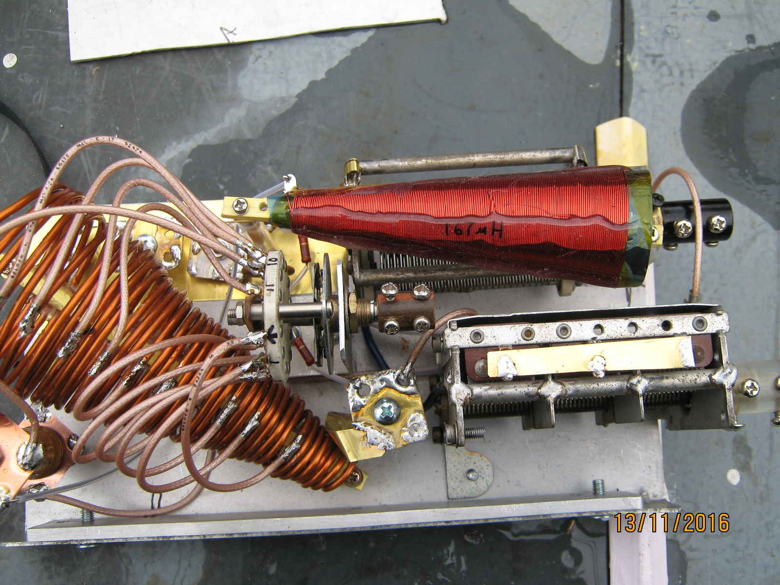
The conical inductor for HF choke attempts to bypass a problem with cylinderical coils and their strange resonances. At some frequncy, the winding length becomes like an equivalent 1/2 wave line, which turns the choke into a short circuit and the central part into a tesla coil , whoose corona will rapidly erode the choke. The stepped pie wound chokes found on classical transmitters are an approximation of the cone inductor. Conical chokes are making a comeback, a firm called CoilCraft is making them for microwave bias lines specifically for their broadband performance. The cone has less common magnetic flux lines linking the turns, this creates a model of many "perfect" individual inductors in series. The cones were discovered in the 1920's but proved unpopular due to the mathematical difficulty in predicting their inductance; and they required for special mandrels for winding them. My RFC cone has 137uH as measured on my GenRad bridge, which is a usefully large inductance for choke applications. The choke will be placed at the "cold end" of the PI output coil. This will eliminate much of the troubles associated with broadband RF chokes. This means that the tap selector switch and the coil and tuning capacitor will be at EHV potential. This is a break with the standard transmitter design orthodoxy and also makes this design hazardous. Be warned if you try to copy this idea.

The purpose of trying a conical inductor in the anode tank is to improve the Q of the inductor. By tradition, the anode PI tank is tapped and switched. The unwanted part of the coil is shorted out. Magnetic flux from the "active" part of the coil is still threading the shorted turns causing a circulating current. This current is subject to ohmic losses and serves only to reduce the amount of energy in the tank circuit, that same energy that you have commited so much time effort and money to produce ! By shorting out the tip of the cone, far less magnetic flux is coupled to the shorted out section. This has the overall effect of increasing the overall Q of the inductance. There is also the benefit of less chance of exiting a stray resonance. Measurements of Q and Inductance on my bridge seems to confirm the soundness of this idea. I should also add that winding the cone was extremely difficult with the heavy gauge wire . The secret is to wind the small end first and not to stop untill the entire winding is completed. The spiral will unwide itself somewhat, never mind, the unwinding is small but does increase the diamter of the cone. Take this into account if the available space is small.
· ESQUEMA 1

· Imagen de una espiral cónica logarítmicas de Vortex Coil

· En la vida animal también hay espiral cónica logarítmicas como el Turritella communis

---
73 Carlos EA1DVY
Carlos EC1T
Ex. EA1DVY
Soria in81
Inició el tema
En la web de Conical Tesla Coil informa como calcular un Inductor conico

La bobina cónica se puede calcular mediante las siguientes fórmulas empíricas de Harold Wheeler, que Tesla estaba usando:
N - número de vueltas
A - diámetro de la base del cono
B - diámetro de la parte superior del cono
H - altura del cono
W = (B - A) / 2 - ancho efectivo de la bobina
Z - longitud de la bobina (¡a lo largo de la hipotenusa!) Z = √ (W 2 + H 2 )
X - ángulo del cono ( sin (X) = H / Z; cos (X) = W / Z )
R = A / 2 + W / 2 - radio medio de la bobina
L 1 = R 2 * N 2 / (9 * R + 10 * H) - componente vertical de la inductancia
L 2 = R 2 * N 2 / (8 * R + 11 * W) - componente horizontal de la inductancia
L = √ [(L 1 * Sin (X)) 2 + (L 2 * cos (X)) 2 ] - inductancia agregada de la bobina
Inductancia en μH, dimensiones en pulgadas.

---
73
Carlos EC1T
Ex. EA1DVY
Soria in81
Inició el tema

Hola a todos.
Me ha parecido muy interesante el tema, pero no me he podido resistir.
Estos lineales están especialmente diseñados para hablar con los Caraconos... ")
jon, ea2sn
Jon, EA2SN / AE2SN
... el que lee mucho y anda mucho vee mucho y sabe mucho. (Don Quijote, libro segundo, capítulo XXV)
Examinador Voluntario para la FCC (EE. UU.) con ARRL-VEC /.../ 4,69BDXCC como EE2A con una vertical y 5-100 W

Pues debo estar más lerdo de lo habitual hoy, porque no me entero:
Aparte de la dificultad constructiva, qué más propiedades tiene la cono-bobina?
(con N, no con Ñ)
Concretamente , que beneficios/mejoras aporta ?
no me ha quedado nada claro....¿?
73,
Jose.
No hay peor sordo que el que no quiere oir,
peor ignorante que el que no quiere aprender,
y yo,sólo sé que no se nada!
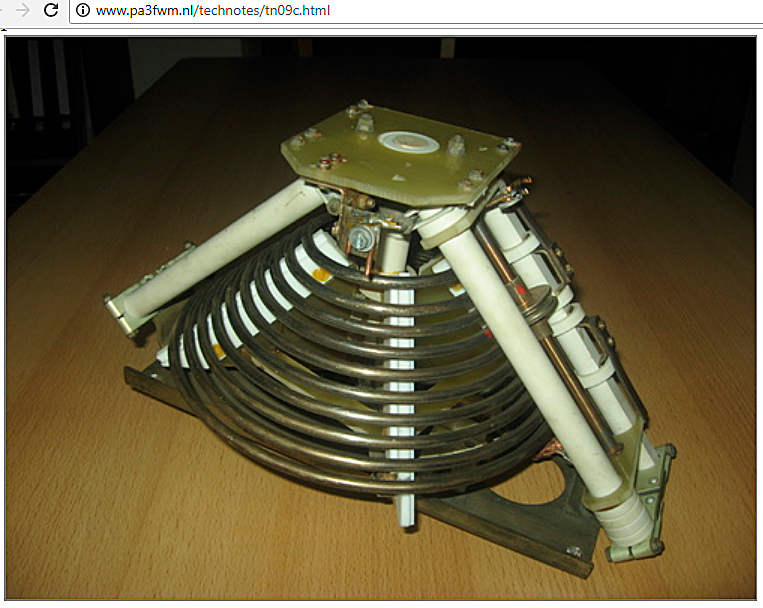
Muy interesante, en su día vi una de rodillo como la de la foto de PA3FWM y me preguntaba lo mismo.
Escribió:Concretamente , que beneficios/mejoras aporta ?
Ahora lo entiendo, evitar las resonancias parásitas.
Si quieres buenas respuestas haz buenas preguntas
73 de Angel, EA2ET.
QDURE - https://qsl.ure.es
Imprime y confirma tus QSL en tan solo tres click.
Nunca fue tan fácil y cómodo
el confirmar tus contactos.
TIENDA ONLINE URE
Publicaciones, mapas, polos, camisetas, gorras, tazas, forros polares y mucho más...
WEBCLUSTER EA4URE
Conoce el nuevo WebCluster de URE, ahora con nuevos filtros e información y compatible con GDURE